1. A Git project page will be created and shared with the instructor.
2. The architecture of the Raspberry Pi Pico will be studied to understand what it is and how it works.
3. The Raspberry Pi Pico will be booted and introduced to the computer system.
4. Using Visual Studio Code (VSCode) or Thonny, the first code will be written to make the LED on the Pico blink, and this will be added to the portfolio page.
5. The circuit will be set up with a breadboard, and an external LED will blink. The concept of LEDs will be explained.
6. The standard method for connecting the LED and Pico to the breadboard will be explained.
7. The LED and Pico will be connected to the breadboard, and a DC motor will be controlled to rotate both clockwise and counterclockwise.
8. A web-based HTML page will be created. On this page, the LED on the Pico and the LED on the breadboard will blink. Additionally, buttons for controlling the rotation of the motor will be added.
9. The rotation of the motor will be controlled within the range of 0 to 180 degrees.
10. The L298 motor driver will be introduced, and its use will be explained with examples from GitHub.
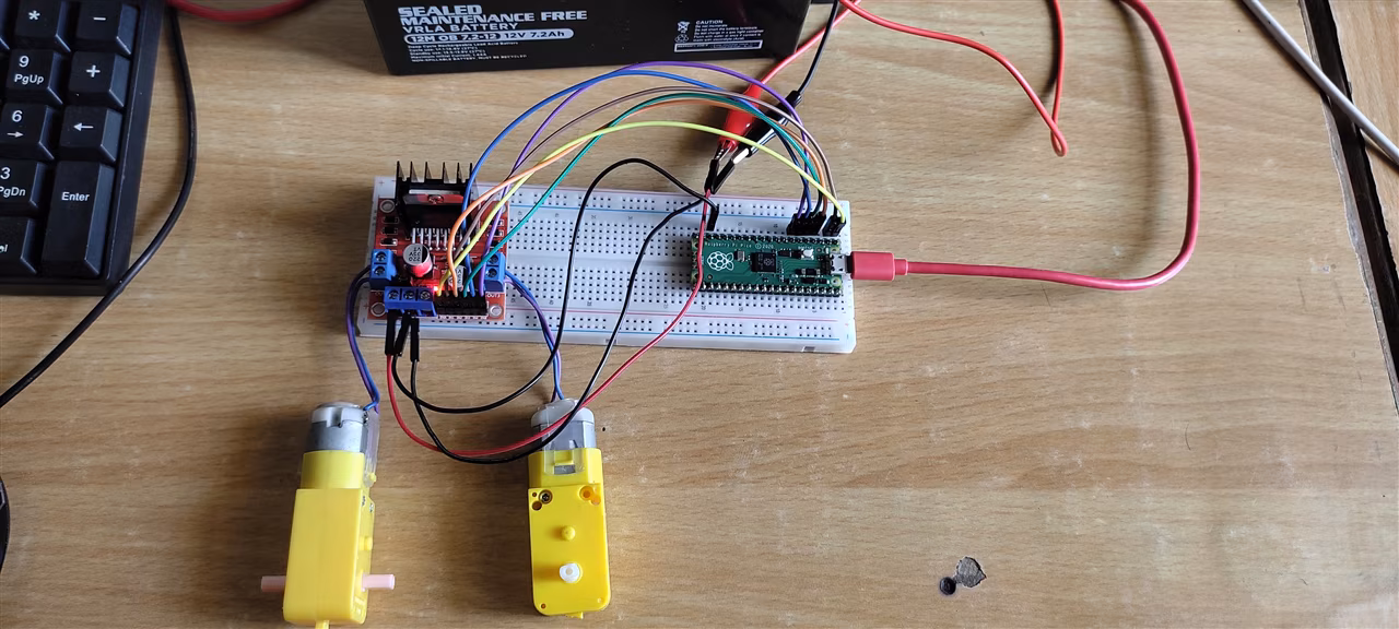
11. The L298 motor driver will be connected to two motors and controlled using the Raspberry Pi Pico.
12. Power management will be researched, and the power issue related to two DC motors, one Pico, and the L298 will be resolved.
13. The robot assembly will be completed.
14. The robot will be tested using the web interface with wired connections, and the buttons on the web page will be updated according to the challenge requirements.
15. The existing Pico will be replaced with the Pico W, and the system will be operated wirelessly. The network topology and web server architecture will be explained.
16. The final portfolio will be completed, including the electronic architecture, programming architecture, and design architecture. A 30-second working video will be uploaded to GitHub and presented to the instructor, Sedat.
Raspberry Pi Pico Architecture:
To begin with, we need to examine the Raspberry Pi Pico’s architecture in depth to comprehend its components and how it operates. The Pico is a microcontroller board built on the RP2040 chip, designed and manufactured by the Raspberry Pi Foundation. It is distinct from the traditional Raspberry Pi single-board computers, as it is a microcontroller rather than a full computer system. Let’s break down its core architecture and functionality step by step.
The RP2040 Chip: The Heart of the Pico:
The Raspberry Pi Pico uses the RP2040 microcontroller, a custom-designed chip by the Raspberry Pi Foundation. The RP2040 is a 32-bit ARM Cortex-M0+ processor, which is specifically designed for embedded systems and low-power applications. Unlike the powerful ARM cores used in full Raspberry Pi computers, the Cortex-M0+ is optimized for efficiency and speed in handling real-time tasks. It operates at a clock speed of up to 133 MHz, providing a solid balance between performance and power consumption. Additionally, the RP2040 chip contains dual cores, meaning it can execute two tasks in parallel (dual-core processing). This is essential for applications that require simultaneous processing, such as controlling multiple sensors or peripherals, which makes it more versatile in embedded projects.
Memory and Storage:
The RP2040 chip on the Raspberry Pi Pico is equipped with 264 KB of SRAM, which is used for temporary data storage. This allows the Pico to handle a range of tasks with moderate memory demands. For long-term storage, the Pico doesn’t have built-in flash storage but provides a slot for external flash memory. Most Raspberry Pi Pico boards come with 2 MB of flash storage, which is used to store code, libraries, and other data necessary for operation. This flash memory is rewritable, meaning you can update the programs stored on the Pico as needed.
GPIO Pins (Interfacing with the Outside World):
One of the most significant features of the Raspberry Pi Pico is its General Purpose Input/Output (GPIO) pins. The Pico offers 26 GPIO pins, which can be configured for input or output and are capable of interacting with a wide range of peripherals, such as sensors, LEDs, motors, and displays. These GPIO pins also support various communication protocols, including I2C, SPI, and UART, which are essential for connecting the Pico to other devices in a system. For example, a sensor might use I2C to communicate with the Pico, while a motor driver might use PWM (Pulse Width Modulation) signals on the GPIO pins to control the motor’s speed and direction. The versatility of these pins makes the Pico ideal for embedded applications where real-time control and communication are crucial.
Power Supply and Efficiency:
The Raspberry Pi Pico can be powered via a micro-USB connector or through external power inputs, typically ranging from 1.8V to 5.5V. The efficient design of the RP2040 chip and the surrounding circuitry allows the Pico to run on very low power, making it suitable for battery-powered or energy-efficient projects. For instance, if you’re building a portable sensor network or a robotics system that requires constant operation without recharging, the power management capabilities of the Pico are essential.
Programming and Software Development:
Programming the Raspberry Pi Pico is straightforward, thanks to the support for various development environments, such as Thonny (a Python IDE) or Visual Studio Code with C/C++ SDK. The RP2040 microcontroller supports programming in both C/C++ and MicroPython, making it flexible for students and professionals alike. MicroPython, a version of Python specifically designed for microcontrollers, provides an easy-to-use environment for beginners, while C/C++ allows for more advanced, performance-critical applications. The Pico can be easily reprogrammed by connecting it to a computer via USB. Upon boot-up, the device appears as a storage device, and you can simply drag and drop your code to it. This feature simplifies the development and debugging process, as you don’t need an external programmer or complex setup.
Peripheral Support: Expanding the Pico’s Capabilities:
While the Raspberry Pi Pico itself is a highly capable microcontroller, its true power comes from its ability to interact with and control various external peripherals. With the help of add-ons and accessories, such as motor drivers, sensors, cameras, and displays, the Pico can be used in a wide range of applications—from building a simple LED blink circuit to more complex robotics or IoT systems. For example, you can connect a servo motor to one of the GPIO pins and control its position with PWM signals. Alternatively, you might connect an ultrasonic sensor to measure distance and then use the Pico to process the sensor data and trigger actions based on the readings.
Development Process and Tools:
The development tools for Raspberry Pi Pico are highly integrated and user-friendly. The most common development environments for Pico programming are:
Thonny IDE: Thonny is an excellent tool for beginners, especially when using MicroPython. It provides an integrated environment where students can write, debug, and execute their code with ease.
Visual Studio Code (VSCode): For more advanced development in C/C++, VSCode is a powerful editor that integrates well with the Pico SDK. It provides advanced features like debugging and IntelliSense, which helps streamline the development process.
Debugging and Optimization:
Since the Raspberry Pi Pico is designed for real-time applications, debugging and optimization are crucial aspects of the development process. Tools like serial output for debugging, along with breakpoints and step-through debugging in your chosen IDE, can be used to track down issues and optimize code. The efficiency of the RP2040 microcontroller ensures that even in time-sensitive applications, the Pico can handle multiple tasks without significant delays.
By studying the architecture of the Raspberry Pi Pico, we gain insight into how microcontrollers work and how they can be programmed to interact with the physical world. Understanding the Pico’s capabilities—its dual-core processor, GPIO pins, power management, and peripheral support—lays the foundation for creating a wide range of embedded systems and robotics projects. Whether you are just starting with embedded systems or looking to expand your knowledge, the Pico is a great tool for learning and experimenting with real-world applications.
Blinking the Onboard LED:
This program demonstrates how to blink the onboard LED of the Raspberry Pi Pico using MicroPython. The primary goal is to familiarize students with fundamental concepts in embedded systems programming, such as controlling GPIO (General Purpose Input/Output) pins, using infinite loops, and introducing timed delays.
The program begins by importing two essential modules: machine and time. The machine module provides low-level access to the Pico’s hardware, and within it, the Pin class is used to define and control GPIO pins. The time module is used for introducing delays between LED toggles, allowing us to control the frequency of the blinking.
Next, the program defines a variable named led, which is initialized as a Pin object. Specifically, it configures GPIO pin 25 as an output pin. On the Raspberry Pi Pico, GPIO 25 is hardwired to the onboard LED, making it a convenient choice for introductory exercises. By setting the pin mode to Pin.OUT, we indicate that this pin will be used to send signals (HIGH or LOW voltage) to control an external component, in this case, the LED.
The program then enters an infinite loop using while True:. This ensures that the following actions repeat continuously for as long as the Pico remains powered. Inside the loop, the statement led.toggle() is used to reverse the current state of the LED—turning it on if it was off, and vice versa. This method simplifies the logic by eliminating the need to manually track the current state of the pin. After each toggle, the program pauses for half a second using time.sleep(0.5). This delay is critical because, without it, the LED would toggle states too quickly for the human eye to perceive the blinking effect.
Overall, this simple program introduces key concepts in embedded programming such as hardware initialization, digital output control, timing, and continuous execution using loops. Saving the file as main.py directly onto the Pico allows the code to run automatically every time the board is powered, making this example an ideal starting point for more complex hardware-interfacing projects.
Program Code:
from machine import Pin
import time

led = Pin(25, Pin.OUT)

while True:
    led.toggle()
    time.sleep(0.5)
Blinking the Breadboard LED:
In this step, we will extend our understanding of digital output control by connecting an external LED to the Raspberry Pi Pico using a breadboard, and then writing a program that blinks this external LED. This introduces both fundamental hardware knowledge and reinforces the GPIO programming concepts previously applied to the onboard LED.
Before writing code, it is essential to understand what an LED is and how it functions. An LED, or Light Emitting Diode, is a semiconductor device that emits light when an electric current passes through it. Unlike regular bulbs, LEDs are polarized components, meaning they have a positive leg (anode) and a negative leg (cathode), and current must flow in the correct direction—from anode to cathode—for the LED to illuminate. LEDs are widely used due to their low power consumption, fast switching time, and long lifespan. However, they must always be used with a current-limiting resistor (typically 220Ω or 330Ω) to prevent damage caused by excessive current.
To begin the hardware setup, place a Raspberry Pi Pico and a LED onto a breadboard. Connect one end of a resistor to the longer leg (anode) of the LED, and then connect the other end of the resistor to a GPIO pin on the Pico (for example, GPIO 15). The shorter leg (cathode) of the LED should be connected directly to the Pico’s GND (ground) pin. This simple circuit allows the GPIO pin to provide voltage to the LED, completing the circuit and turning the LED on.
On the software side, we will write a MicroPython program similar to the previous example, but this time we will control GPIO 15 instead of GPIO 25. The code will use the machine module to configure GPIO 15 as an output, and the time module to create regular time intervals for blinking. Inside an infinite loop, the program will toggle the LED’s state and pause for a short delay (e.g., 0.5 seconds), creating a visible blinking effect.
This exercise reinforces the connection between hardware components and software control, highlighting how microcontrollers like the Pico interact with the physical world. It also introduces students to prototyping techniques using breadboards, which is a vital skill in embedded systems and robotics development.
Program Code:
from machine import Pin
import time

# Create a Pin object for GPIO 15 (connected to external LED)
led = Pin(15, Pin.OUT)

# Blink the LED in an infinite loop
while True:
    led.toggle()       # Change the LED state (ON -> OFF or OFF -> ON)
    time.sleep(0.5)    # Wait for 0.5 seconds
Blinking the LED and Rotating DC Motor Through L298:
This MicroPython program controls both an LED and a DC motor connected to the Raspberry Pi Pico through a breadboard. The program continuously alternates between turning the LED on, rotating the DC motor forward, then rotating it backward, before stopping the motor and turning off the LED. The process is repeated in a continuous loop.
The program begins by importing the necessary modules: Pin from the machine module and the time module. The Pin class allows the program to control the GPIO pins on the Raspberry Pi Pico, while the time module provides the ability to pause the execution of the code for a set duration, which is essential for motor rotation and LED timing.
In the code, GPIO 16 is used to control the LED attached to the breadboard. A Pin object called led is created, and its state is controlled using the functions turn_on_led() and turn_off_led(). The function turn_on_led() sets the GPIO pin to HIGH (1), turning the LED on, and turn_off_led() sets it to LOW (0), turning the LED off. These functions help manage the LED's state throughout the program.
For controlling the DC motor, GPIO 14 and GPIO 15 are used to send control signals to the IN1 and IN2 pins of the L298N motor driver, respectively. The motor's direction is controlled by setting these pins to HIGH or LOW. To rotate the motor in a forward direction (clockwise), IN1 is set to HIGH and IN2 is set to LOW, which is achieved in the function rotate_motor_right(). Conversely, to rotate the motor backward (counterclockwise), IN1 is set to LOW and IN2 is set to HIGH, which is handled in the function rotate_motor_left().
The motor's movement is timed using the time.sleep() function. The motor runs forward for 2 seconds in rotate_motor_right(), then stops for 1 second by setting both IN1 and IN2 to LOW. Afterward, the motor runs in reverse for another 2 seconds in rotate_motor_left(), and again stops for 1 second. This process is continuously repeated in the while True loop, where the LED and motor alternate between their respective states.
In summary, this program introduces students to controlling both digital outputs (LED) and motor direction using GPIO pins on the Raspberry Pi Pico. It demonstrates the use of control logic to manage the state of hardware components, time delays to create observable effects, and looping to create a continuous pattern of operations. The use of functions such as turn_on_led(), turn_off_led(), rotate_motor_right(), and rotate_motor_left() modularizes the code, making it easier to understand and extend. This is a fundamental concept in embedded systems programming where hardware control is performed based on time intervals and logical conditions.
Program Code:
from machine import Pin
import time

led = Pin(16, Pin.OUT)
motor_in1 = Pin(14, Pin.OUT)
motor_in2 = Pin(15, Pin.OUT)

while True:
    led.toggle()
    motor_in1.value(1)
    motor_in2.value(0)
    time.sleep(2)
    motor_in1.value(0)
    motor_in2.value(1)
    time.sleep(2)
Rotating The Car 180 Degrees to Left and Right:
This program allows a Raspberry Pi Pico to control the rotation of a robot by turning it 180 degrees to the left and 180 degrees to the right. It uses two DC motors to provide the necessary movement, with each motor controlled via two GPIO pins. The goal of this program is to make the robot turn precisely by rotating both motors in the appropriate direction for a set duration. The rotation is timed using time.sleep() to make the motors run for a fixed period, after which they are stopped, causing the robot to complete a 180-degree turn.
The program begins by defining motor control pins using the machine.Pin class to create four output pins: two pins for each motor's direction control. Motor 1 is connected to GPIO 14 and GPIO 15, while motor 2 is connected to GPIO 16 and GPIO 17. The function of these pins is to control the direction of rotation of each motor. By setting these pins to HIGH or LOW, we determine the direction the motor spins. For instance, when IN1 is set to HIGH and IN2 is set to LOW, the motor spins in one direction (forward), while switching them will cause the motor to rotate in the opposite direction (backward).
The rotate_right() function is responsible for rotating the robot 180 degrees to the right. In this function, both motors are set to rotate forward, which causes the robot to spin in place. The duration of the rotation is controlled by time.sleep(2), which keeps the motors running for two seconds, sufficient for the robot to complete a 180-degree turn. After the rotation, both motors are stopped by setting all control pins to LOW.
Similarly, the rotate_left() function is used to rotate the robot 180 degrees to the left. To achieve this, the directions of both motors are reversed by setting IN1 to LOW and IN2 to HIGH for both motors. This will cause the motors to rotate in the opposite direction, making the robot turn left. Like the rotate_right() function, the rotation duration is set to two seconds using time.sleep(2).
After each rotation, there is a brief pause of one second between actions, which allows the robot to come to a complete stop before the next action is executed. The main loop then alternates between rotating the robot to the right and left, with a pause between each turn. This loop continues indefinitely, making the robot perform a continuous series of rotations.
The code structure is simple and modular, with distinct functions for rotating the robot right and left, making the code easy to extend and modify. If needed, the program could be modified to adjust the duration of the rotations or even include features such as speed control by using PWM (Pulse Width Modulation) for controlling motor speed, rather than just turning them on or off.
In summary, this program demonstrates basic motor control and timed rotations, which are fundamental skills in robotics. The control of two DC motors via GPIO pins provides the necessary movement for the robot to turn, while the timing mechanism ensures precise control of the rotation. This simple yet effective method forms the basis for more complex robot behaviors and is a building block for many robotic navigation tasks.
The L298 Motor Driver is a popular and widely-used integrated circuit (IC) designed to control the direction and speed of DC motors and stepper motors. It is a part of the H-Bridge family, which allows the motor to rotate in both directions, making it ideal for applications such as robotics, automation, and small electronic projects. The L298 is designed to drive motors with higher current requirements than the typical GPIO pins of microcontrollers like the Raspberry Pi Pico or Arduino, which can only provide limited power (around 20–40 mA per pin). The L298 can supply up to 2A of continuous current, making it suitable for most small- to medium-sized motors.
How the L298 Works:
The L298 Motor Driver uses an H-Bridge configuration, which is a type of electronic circuit used for driving motors in both directions. It contains four switches (transistors) arranged in an "H" shape, allowing current to flow through the motor in either direction, depending on how the switches are controlled. The key benefit of using an H-Bridge is that it allows the motor to rotate clockwise or counterclockwise by controlling the direction of current flow.
When controlling a DC motor, two input pins (IN1 and IN2) are used to determine the direction of rotation. By applying either a HIGH or LOW signal to each of these pins, the L298 switches the current between the two motor terminals, causing the motor to rotate in the desired direction. The ENA pin (Enable A) controls whether the motor is powered, and the OUT1 and OUT2 pins are connected to the motor terminals. The ENA pin, when set HIGH, allows current to flow to the motor; if set LOW, the motor is disabled. ENA can also be connected to a PWM signal for controlling motor speed by adjusting the duty cycle, allowing for variable speed control.
Pin Description of the L298:
The L298 has a variety of pins that control motor direction, speed, and enable functions. Here's an overview of the key pins:
IN1, IN2, IN3, IN4: These pins are the input control pins used to drive the motor in either direction. For a single motor, IN1 and IN2 control the rotation direction; for a dual motor setup, IN3 and IN4 are used in the same manner.
ENA (Enable A): This pin is used to enable or disable the motor. When ENA is HIGH, the motor will operate, and when LOW, it will stop.
ENB (Enable B): For dual-motor configurations, ENB controls the second motor in a similar manner to ENA.
OUT1, OUT2: These pins are connected to one terminal of the motor. The current flows through these pins depending on the input states of IN1 and IN2.
GND: This pin provides the common ground for the L298 and the external power supply.
VCC: This pin is connected to the positive terminal of the power supply that drives the motor, typically ranging from 5V to 35V depending on the motor’s requirements.
VSS: This pin is connected to the logic supply voltage (typically 5V), which powers the internal logic of the L298.
Hardware and Electrical Characteristics:
The L298 is capable of driving motors with voltages ranging from 4.5V to 46V, making it suitable for a wide range of motor types. The current rating for each motor channel is typically 2A continuous, with peak currents reaching 3A for short durations. The IC is also equipped with built-in diodes for flyback protection, which protect the driver from voltage spikes generated when motors are turned off.
In terms of power efficiency, the L298 is a linear regulator type driver, meaning it does not provide the most efficient power conversion. The efficiency of the L298 is typically around 40-50% because of the voltage drop across the internal transistors when the motor is running. This is a trade-off for the simplicity and robustness of the driver. For more energy-efficient solutions, MOSFET-based motor drivers like the TB6612 or L293 are often preferred, as they have significantly higher efficiency and lower heat generation. However, the L298 is still widely used due to its availability, reliability, and ease of integration.
Software Control:
In terms of software, the L298 does not require complex programming or dedicated hardware interfaces. You simply send digital HIGH or LOW signals to the input pins (IN1, IN2) and control motor speed via PWM signals on the ENA or ENB pins. The use of PWM (Pulse Width Modulation) allows for fine-grained speed control by adjusting the duty cycle of the signal. The higher the duty cycle, the faster the motor spins.
For example, on platforms like Arduino or Raspberry Pi, you can use the digitalWrite() function to set the motor direction and the analogWrite() function (if using a PWM-enabled pin) to control the motor's speed. Similarly, on Raspberry Pi Pico, you can control the motor with the machine.Pin and machine.PWM classes.
RAM, CPU, and Storage:
The L298 does not contain any CPU, RAM, or storage because it is a pure analog motor driver IC. It is not a microcontroller but rather a power switch for controlling high-current devices like motors. Its sole purpose is to interface with a microcontroller or other digital control device to enable motor control. Therefore, it does not require onboard memory or a processor.
Instead, the L298 relies on the signals from external controllers (like the Raspberry Pi or Arduino) to dictate motor movement. It only handles the power requirements and switching of current to the motors based on those control signals.
Applications and Use Cases:
The L298 is most commonly used in applications where precise control over the rotation of motors is required, such as in robotics, automation, motorized projects, and even model trains. It is often used in beginner robotics kits due to its simple interface, ability to drive larger motors, and ease of use in educational projects.
Electrical Efficiency of the L298 Motor Driver:
The L298 Motor Driver is an integrated circuit designed to control DC and stepper motors by using an H-Bridge configuration, which allows for bidirectional motor control. It can handle up to 2A of continuous current per motor and can operate at voltages between 4.5V and 46V. The L298 works by controlling the direction of current flow to the motor through IN1 and IN2 pins, and it uses PWM signals for speed control via the ENA pin. However, the L298 is known for its low efficiency (around 40-50%) because it uses BJTs (bipolar junction transistors), which have a significant voltage drop (around 1-1.5V) across them during operation. This leads to power loss as heat, making the L298 less energy-efficient compared to MOSFET-based motor drivers, which are more efficient and produce less heat. Despite its inefficiency, the L298 is still widely used in educational and hobbyist projects due to its affordability, simplicity, and reliable performance for moderate power applications.
Conclusion:
In summary, the L298 Motor Driver is a reliable and straightforward solution for controlling DC motors and stepper motors. It provides flexibility in motor direction control and speed control via external PWM signals, making it an excellent choice for simple robotics and automation projects. However, its lower efficiency and heat generation make it less suitable for high-performance or power-sensitive applications. Despite this, it remains a popular choice due to its robustness, ease of use, and availability, particularly in educational and hobbyist environments.
Program Code Example:
from machine import Pin
import time

# Motor control pins
motor_in1 = Pin(14, Pin.OUT)
motor_in2 = Pin(15, Pin.OUT)

# Function to rotate motor forward (clockwise)
def rotate_motor_right():
    motor_in1.value(1)
    motor_in2.value(0)
    print("Motor rotating right (clockwise)")

# Function to rotate motor backward (counterclockwise)
def rotate_motor_left():
    motor_in1.value(0)
    motor_in2.value(1)
    print("Motor rotating left (counterclockwise)")

# Main loop
while True:
    rotate_motor_right()
    time.sleep(2)
    rotate_motor_left()
    time.sleep(2)
Power Management in 2 DC Motor, 1 Pico and 1 L298:
In this step, the focus is on power management for a system consisting of two DC motors, a Raspberry Pi Pico, and an L298 motor driver. Each component has its own power requirements, and ensuring the system operates efficiently involves managing these power needs effectively.
The Raspberry Pi Pico typically requires 5V to operate, which can be supplied through the USB connection or an external power source via the VSYS pin. The L298 motor driver, on the other hand, is designed to control DC motors and can handle higher voltage levels (typically from 5V to 12V or more). The two DC motors also require an external power supply, as the Pico cannot provide enough current to drive them directly.
The power issue arises because the Pico and L298 require different power sources: while the Pico can be powered through its USB connection or from a low-voltage power supply, the L298 needs a higher voltage to power the motors. Additionally, the current demand from the motors, especially under load, can cause voltage drops or excessive heat dissipation in the L298, leading to inefficiency and potential damage if not managed properly.
To resolve these issues, a separate power supply should be used for the motors, while the Pico can be powered through USB or a dedicated 5V source. The L298 should be supplied with a voltage matching the motor’s requirements, and the system's common ground should be connected across the Pico, the L298, and the external motor power source to ensure stable operation. Additionally, incorporating a voltage regulator or buck converter can help step down the voltage for the Pico, reducing power loss and improving efficiency. Proper heat management (using heat sinks for the L298, for example) is also important to prevent thermal shutdown or damage. This approach ensures that each component gets the appropriate power while preventing power conflicts or inefficiencies.
Controlling the Pico Car Through HTML Web Page:
This MicroPython program enables the Raspberry Pi Pico to act as a web server, allowing remote control of an LED and a DC motor via a simple HTML interface. The program utilizes the network and socket modules to set up the web server, which serves an HTML page containing buttons to toggle the LED and control the direction of the motor. The code also connects the Pico to a Wi-Fi network, allowing it to be accessed from any device connected to the same network.
The program begins by establishing a connection to the Wi-Fi network. It uses the network.WLAN class to activate the Wi-Fi interface of the Pico and connect to the specified SSID and password. Once the connection is successful, the program prints the Pico's IP address to the serial monitor, enabling users to access the web server using this address.
Setting Up the Web Server:
Next, the code sets up a simple web server using the socket module. The server listens for HTTP requests on port 80 and responds with an HTML page. This page is served directly from the Pico, and it contains two main sections: one for LED control and one for motor control. Each section includes a button, which, when clicked, triggers a JavaScript function that sends a request back to the Pico's web server to perform an action. The toggleLED() function sends a request to the /toggle_led URL, and the rotateMotor(direction) function sends a request to the /rotate_motor URL with the direction specified as either "right" or "left."
Controlling the LED:
The toggleLED() function is used to toggle the state of the onboard LED connected to GPIO 16. When the button is clicked, the server receives a request to toggle the LED. The Pico's response updates the state of the LED by setting the GPIO pin high or low, thus turning the LED on or off.
Controlling the Motor:
Similarly, the motor control section includes two buttons: one for rotating the motor clockwise (right) and another for rotating it counterclockwise (left). These buttons send a request to the server, and the motor's direction is controlled by the state of GPIO 14 and GPIO 15, which are connected to the L298N motor driver. When the "Motor Right" button is clicked, GPIO 14 is set to HIGH and GPIO 15 is set to LOW, causing the motor to rotate forward. Conversely, clicking the "Motor Left" button sets GPIO 14 to LOW and GPIO 15 to HIGH, causing the motor to rotate in the opposite direction.
Web Page Updates:
The server responds to each request by sending the HTML page back to the client, ensuring that the web page is always up-to-date with the current state of the LED and motor. This is done by checking the incoming request URL and performing the corresponding action. After each action (LED toggle or motor rotation), the server sends the updated HTML page to the browser, allowing the user to interact with the hardware in real time.
Conclusion:
In conclusion, this project demonstrates how to integrate basic web control into embedded systems using a Raspberry Pi Pico. By leveraging MicroPython and simple socket programming, the program allows users to control physical components, such as LEDs and motors, through a web browser. This setup provides a solid foundation for more complex IoT applications where devices can be remotely controlled over a network. The modularity of the code also allows easy expansion, such as adding more controls, adjusting motor speed with PWM, or integrating sensors for feedback in future projects.
Program Code:
import network
import socket
from machine import Pin
import time
# Setup for LED and motor control
led = Pin(16, Pin.OUT) # LED on GPIO 16
motor_in1 = Pin(14, Pin.OUT) # Motor control pin 1
motor_in2 = Pin(15, Pin.OUT) # Motor control pin 2
# Connect to Wi-Fi
wifi_ssid = 'your_wifi_ssid'
wifi_password = 'your_wifi_password'
wifi = network.WLAN(network.STA_IF)
wifi.active(True)
wifi.connect(wifi_ssid, wifi_password)
while not wifi.isconnected():
time.sleep(1)
print("Connected to WiFi")
print("IP Address:", wifi.ifconfig()[0])
# Web server setup
html = """
Control LED and Motor
Raspberry Pi Pico Web Control
"""
addr = socket.getaddrinfo('0.0.0.0', 80)[0][-1]
s = socket.socket()
s.bind(addr)
s.listen(1)
while True:
cl, addr = s.accept()
request = cl.recv(1024)
request = str(request)
# Control LED
if '/toggle_led' in request:
led.value(not led.value())
# Control motor
if '/rotate_motor' in request:
direction = request.split('direction=')[1].split(' ')[0]
if direction == 'right':
motor_in1.value(1)
motor_in2.value(0)
elif direction == 'left':
motor_in1.value(0)
motor_in2.value(1)
cl.send('HTTP/1.1 200 OK\r\n')
cl.send('Content-Type: text/html\r\n')
cl.send('\r\n')
cl.send(html)
cl.close()